Tajima Error Codes: Full List and Quick Fixes
This post contains affiliate links. As an Amazon Associate, Latest Embroidery earns from qualifying
purchases, at no extra cost to you. Learn more.
When Tajima and Inbro embroidery machines throw codes like 4.2B2 or 8.211, downtime climbs and frustration rises.
This practical diagnostic matrix maps codes to concrete actions, with model-specific checks for IB-RSC1201 vs IB-C1201 II, and data-quality steps (1 DFA, 2B2–2B5). It covers hardware inspection and wiring checks, including connectors, fuses, and sensor cables, plus recommended hand tools and spare parts, and a step-by-step workflow you can execute in under an hour to minimize downtime and keep production moving.
For deeper context, these resources offer Tajima and Inbro code explanations and real-world tips: Decode Tajima error codes quickly, Tajima Machine Error List, Inbro Embroidery Machine Error Codes: Complete Troubleshooting Guide, Inbro IB-C1201 Mastery Guide.
Keep reading for an hour-or-less workflow that turns error codes into action, so you can get back to production quickly and with confidence.
Interested in a capable upgrade? Here’s a catalog:
Shop embroidery machines on Amazon →
How to read Tajima and Inbro error codes
Short on time? If you only take one thing from this guide: Machine oil & cleaning kit — most “faulty machine” problems are lint and a dry hook race.
When Tajima and Inbro machines throw a fault, you need a fast, repeatable path to get back to productive sewing. This section translates the most commonly seen codes into concrete, immediately runnable actions, with model-specific notes for IB-RSC1201 and IB-C1201 II. You’ll find a concise code-to-action map, guidance on data handling for 2B2–2B5, and practical hardware context to keep on hand while you troubleshoot. Real-world workflows often involve runs up to 27, 000 stitches and dozens of stored designs, so the steps below assume a production mindset but stay tight on what to verify first.
Market context and tool availability matter too: the industry continues to grow with mixed-use software, compatible hoops like MaggieFrame magnetic systems, and design-optimization tools that help you simulate stitch density before you stitch. Keeping a compact diagnostic kit, test indicators, a reliable power source, and up-to-date firmware notes, lets you triage faster and minimize downtime.
Understand Tajima/Inbro error codes at a glance
This code-to-action map covers 4.2B2, 5.2B3, 6.2B4, 7.2B5, and 8.211 with the exact recovery steps you can execute immediately. The actions emphasize quick serial/cable verifications, power cycling, and ensuring design data compatibility. For each code, a model-specific note follows to help you decide if IB-RSC1201 or IB-C1201 II requires a different approach.
Model checks: IB-RSC1201 vs IB-C1201 II
IB-RSC1201 and IB-C1201 II share core electronics, but differences in the joint board harness, encoder wiring, and firmware notes can shift how you approach the same fault. For IB-RSC1201, start with harness inspections and F1/F2 fuse checks, then verify the joint board connectors for oxidation or loose seats. For IB-C1201 II, focus on encoder cables and head alignment calibration, because this model tends to surface data-compatibility issues when you reload large design stashes or export from newer software. In both, re-enter or re-save design data when prompted by a code like 8.211, and confirm data integrity before re-running.
Data-end indicators: recognize when a 1 DFA identifier signals end-of-sequence concerns
A 1 DFA identifier often marks the end of a data sequence rather than a machine fault. Treat this as a cue to truncate the input stream or reformat the incoming design data to fit the machine’s expected sequence length. If you see 1 DFA during a run, pause, reset the data path, and re-import a clean version of the job file. This prevents the machine from attempting a partial or corrupted stitch sequence that leads to skipped steps or misregistered stitches.
Data formatting guidance for 2B2–2B5 to prevent reoccurrence
When preparing 2B2–2B5 designs, standardize the export format to a single, non-overlapping color map and ensure stitch-density settings align with the hoop and fabric. Use a consistent color order, avoid nested or nonstandard color tags, and re-save after every change. Keep a small library of tested 2B2–2B5 templates that you know behave well on IB-RSC1201 and IB-C1201 II. For ongoing operations, create a quick-reference data sheet that lists the required sequence length and the maximum allowed stitch count per run to prevent end-of-sequence hiccups.
Hardware context and diagnostic aids
Prepare for a standard industrial input: 110V, 3A input power. Have spare fuses F1 250V/3A and F2 250V/4A, plus a 6.3A noise filter on hand. Diagnostic aids like MaggieFrame magnetic hoops, Buzz Tools for design-optimization and stitch-density simulation, and Embroidery Tool Shed for color conversion and hooping are invaluable for validating data and optimizing stitch paths before you sew. Maintain notes on TEST_X_MOVE and DIOS 1.53 firmware for quick reference when you’re stepping through head movements and firmware-specific quirks. Concrete workflow context: runs up to 27, 000 stitches and nearly 200 stored designs become a useful scale reference for planning maintenance windows and data re-entry tasks.
Immediate steps to keep you productive
Key actions to perform at the start of troubleshooting: verify serial connections, restart devices, inspect cables, and confirm design data compatibility. If a code points to data concerns, re-enter or re-save the relevant file, and adjust the data formatting specifically for 2B2–2B5. For end-to-end workflow resilience, incorporate a quick data-check checklist into your setup routine and, whenever possible, validate with a short test run using TEST_X_MOVE and a small stitch pattern. Embrace a standardized toolkit and a few validated templates so you don’t reinvent the wheel with every fault.
Seven steps to clear a Tajima error code
When Tajima and Inbro embroidery systems throw codes, a calm, methodical workflow minimizes downtime and keeps production moving. This step-by-step diagnostic checklist is designed for rapid root-cause resolution, aligning with DIOS firmware considerations and common data-format requirements like the 1 DFA end-of-sequence tag. It combines practical hardware checks with software-design data review to cover the most persistent error scenarios on Tajima/Inbro outfits.
Industry dynamics show embroidery remains a high-growth segment, with market analyses highlighting steady demand for faster, more reliable machines and smarter diagnostics as throughput rises. That backdrop reinforces the value of a repeatable, end-to-end procedure you can trust on the shop floor, backed by recent firmware notes and data integrity practices used by professionals in the field.
Step 1: Power down and visually inspect cables
Begin with a full safe shut-down: power off, unplug from the mains, and wait a moment for all capacitors to discharge. Visually inspect every cable and harness within reach for abrasion, kinks, or looseness. Check the main power, encoder, and network cables, as loose or damaged lines are a frequent source of intermittent error codes. If any wear is visible, replace or reseat the connector, then proceed to Step 2.
Step 2: Verify serial connections are seated firmly
Re-seat all serial and ribbon connections involved in the control chain. A firm seating often resolves communication faults that appear as data or tape/read errors. After reseating, perform a complete power cycle: unplug, wait 10–15 seconds, then plug back in and boot. During startup, listen for normal beeps and observe that the control panel initializes without stray signals. This reset helps ensure the machine’s control logic starts from a clean state.
Step 3: Observe startup indicators for abnormal lights or beeps
Watch the diagnostic LEDs and listen for timing patterns on power-up. Abnormal beeps or unusual light sequences typically indicate specific fault areas (board, encoder, motor drive, or sensor). Compare observed indicators with DIOS or Inbro documentation for the exact code interpretation, then log the pattern for cross-checking with the current fix-it chart. If indicators appear normal, you can move to the motion-check stage with TEST_X_MOVE in Step 4.
Step 4: Run a TEST_X_MOVE diagnostic to assess motion
Initiate the TEST_X_MOVE command to exercise X-axis motion and verify encoder feedback is synchronized with actual movement. Watch for smooth acceleration, consistent step counts, and stable end stops. Any irregular waveform, skipped steps, or encoder chatter points to misalignment, belt tension, or sensor issues. If motion is inconsistent, note the affected axis and revisit connections and mechanical clearances before proceeding to Step 5. In many shops, technicians run repeated TEST_X_MOVE cycles to confirm resolution or to reveal intermittent faults that appear only under load.
Step 5: Check firmware notes and version requirements (DIOS 1.53) and update if recommended
Consult the latest firmware notes for your DIOS version and confirm whether DIOS 1.53 is recommended for your model. Firmware updates can improve error handling, encoder calibration, and compatibility with design data formats, reducing recurring codes after a restart. If 1.53 or newer is advised, perform the update following the manufacturer’s standard process, then reboot and re-test starting from Step 1 to confirm the fix. Firmware notes often highlight known issues related to specific error codes, so this step helps align your hardware with current software expectations.
Step 6: Validate design data compatibility; re-enter or re-save files and look for the 1 DFA end-of-sequence tag
Design data integrity is a common culprit behind persistent codes. Open the design in the original Tajima-compatible software and re-save in the machine’s accepted format. Look for the 1 DFA end-of-sequence tag, which signals clean termination of the stitch sequence. If the tag is missing or corrupted, re-export the design, ensuring no extra trailing data or garbled codes at the end of the file. This step is especially important when diagnosing recurring 2B-series codes, which often trace back to data formatting issues.
Step 7: Persisting codes? adjust 2B2–2B5 formatting and perform a small test stitch
For codes tied to 2B2–2B5 formatting, verify tape, reader, and stitch-data formatting compatibility with Tajima/Inbro standards. Re-save the file with clean 2B2–2B5 formatting, then run a small, controlled stitch to confirm the fix. If the small test stich completes without error, gradually ramp to a full test piece. If issues persist, escalate with service support, carrying forward the data captured in Steps 1–6 to accelerate diagnosis.
Research-backed context notes: embroidery market intelligence from 2024–2034 shows sustained growth driven by customization and on-demand manufacturing, underscoring the value of rapid, reliable diagnostic workflows on high-throughput Tajima/Inbro systems. Meanwhile, industry chatter emphasizes that firmware revisions (like DIOS 1.53) and robust data handling (1 DFA tagging) are among the top levers for reducing downtime and maintaining throughput in modern shops.
Data quality and file handling: re-enter/save, 1 DFA, 2B2-2B5

Design data quality drives how Tajima and Inbro interpret stitch instructions, especially on large designs. Subtle formatting quirks or hidden sequence flags can trigger end-of-run faults or density hotspots that slow production. Market analysis shows embroidery remains a growing segment, with industry reports projecting meaningful expansion through the next decade, underscoring the need for clean data pipelines as designs scale. A disciplined data hygiene routine reduces downtime and boosts yield on large runs.
In practice, aligning data across the Tajima/Inbro workflow means treating end-of-sequence signaling as a controllable tag and re-entering or re-saving files to reset latent sequence flags. The guidance here is hands-on and repeatable: re-enter/save to enforce a clear 1 DFA end-of-sequence tag, and apply targeted formatting strategies to prevent end-of-run surprises when stitching large designs.
Data quality and 1 DFA re-entry/save
Re-enter or re-save the design to reset potential sequence flags that can accumulate during edits or transfers. Ensure the sequence tag is clearly defined as 1 DFA at the end of the file so the machine recognizes a clean stop. This simple step helps Tajima and Inbro avoid misinterpreting trailing data as a new run, which frequently manifests as run-time faults across large files.
When you re-save, verify that the header and end-of-file codes align with your project’s color and hoop plan. Maintaining a consistent 1 DFA tag reduces the chance of subtle sequencing errors cascading into 2B2–2B5 end-of-run concerns later in production.
2B2–2B5 formatting adjustments to prevent end-of-run issues
Codes in the 2B2–2B5 range relate to end-of-run signaling and data boundaries. Targeted formatting ensures end codes are paired correctly and that no stray bytes resemble data that could trigger a fresh run. In practice, validate the end-of-sequence tag during re-entry (the 1 DFA signal) and trim any residual data that could be misinterpreted as a new start. This minimizes end-of-run faults when handling large stitch files and helps preserve stitch continuity across color changes and density transitions.
Density simulation with Buzz Tools to identify data hotspots
Before loading to the machine, run a density simulation in Buzz Tools to preview stitch clustering. BuzzSize can recalculate density by color, revealing hotspots where data concentration may cause slowdowns or tension issues. Use the results to redistribute density or split large fills into smoother gradients, reducing areas that could trigger end-of-run anomalies (2B2–2B5) in high-stitch-count sections. Buzz Tools’ density adjustments preserve geometry while improving stitch-flow and machine efficiency.
Color conversion and hoop alignment with Embroidery Tool Shed
Use Embroidery Tool Shed Plus to convert colors across brands and ensure hoop alignment is consistent with the design frame. Proper color sequencing and accurate hooping alignment cut data-related faults at the source by preventing color-change misreads and misaligned stitch starts. The tool’s alignment utilities help position designs within the hoop’s safe margins, reducing edge distortions that often appear as data faults during long runs.
Controlled test run and documentation
Document every change and verify with a controlled test run of roughly 1, 000–2, 000 stitches. This smoke test validates 1 DFA signaling, 2B2–2B5 formatting, and density smoothing in a manageable window before committing to large-scale production. Recording outcomes, stitch count, run time, and any flagged codes, creates a repeatable baseline for future big-design work.
Hardware and electrical checks for Tajima/Inbro
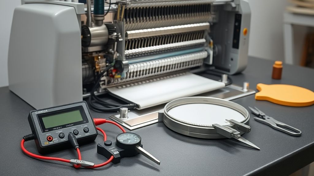
In many Tajima/Inbro machines, error codes can stem from hardware or electrical quirks just as readily as from software or digitizing data. A systematic hardware check reduces downtime and supports long-term reliability in active production environments. Market trends show the embroidery sector is expanding, with steady growth and rising adoption of digital workflows, making dependable electrical health a key maintenance pillar for shops relying on Tajima/Inbro systems. Firmware updates and connectivity improvements continue to roll out, but solid power quality and solid interconnects remain the first line of defense against false or recurring error codes.
Use the following checklist to verify electrical integrity, confirm component health, and document startup behavior. This approach aligns with best practices in preventative maintenance and helps build a maintenance history that informs future corrections or upgrades.
110V power supply stability
Confirm the machine is fed from a stable 110V supply and that voltage stays within tolerance during operation. Record voltages at idle and under load to detect sags or surges that could trigger hardware faults. A noisy or fluctuating supply is a common precursor to sporadic error codes on precision embroidery hardware.
- Measure line voltage at the machine input with a calibrated digital voltmeter; target 110V ±5% (roughly 104.5–115.5V).
- Check for voltage dips when the motor drivers engage or when a service cycle starts; if dips exceed tolerance, relocate to a dedicated circuit or install a voltage stabilizer/UPS.
- Document any transient events or brownouts in your maintenance log for trend analysis.
Inspect and test fuses: F1 250V/3A and F2 250V/4A
Fuses are the primary line-of-defense against overcurrent events. A blown fuse not only halts operation but can mask other issues if replaced without addressing root cause. Replace only with the specified ratings and verify fuse continuity after changes.
- Power down, unplug the machine, and discharge residual energy before handling fuses.
- Visually inspect F1 (250V/3A) and F2 (250V/4A); replace any blown or discolored units with exact ratings.
- After replacement, recheck current draw during startup to confirm no abnormal spikes.
Check the 6.3A noise filter and its connections for signs of wear
The 6.3A noise filter helps suppress conducted interference that can corrupt data lines or trigger misreads on startup indicators. Worn or loose connections can mimic or contribute to error codes during power-on.
- Inspect the filter for signs of heat damage, discoloration, frayed leads, or loose connectors.
- Reseat both ends of the filter and ensure secure, clean connections to the power rail and the machine’s control board.
- Replace the noise filter if any signs of wear, corrosion, or elevated operating temperature are observed.
Inspect and reseat all relevant serial/data cables and connectors
Loose or oxygen-starved data chains can cause intermittent errors. A thorough reseat ensures clean signal paths between power, control boards, and I/O devices.
- Power down and unplug, then disconnect and reseat all serial and data cables (main controller, I/O boards, and peripheral connectors).
- Check for damaged headers, bent pins, or corroded contacts; replace damaged connectors as needed.
- Route cables to minimize tension, bending, and interference; secure with appropriate clips to avoid movement during operation.
Document power-on self-tests and note any anomalies in indicators or beeps
Power-on self-tests (POST) reveal early hardware faults through indicator LEDs and beeps. Document the sequence and any deviations to build a traceable record of hardware health.
- Boot the machine and observe all startup indicators; record timing, color changes, and beep patterns.
- Note any persistent error codes, unusual LED sequences, or failed self-checks.
- Use the log as a baseline for future maintenance planning and to identify recurring hardware issues.
Record the results to track recurring hardware issues and inform maintenance planning
Maintaining a structured hardware log supports trend analysis and proactive maintenance scheduling, reducing unscheduled downtime as production demands grow. Correlate voltage, fuse status, noise filter integrity, cable seating, and POST observations to refine corrective actions and plan component replacements before failures occur.
- Enter date, machine ID, voltage readings, fuse status, connector condition, POST results, and any anomalies.
- Review quarterly to identify patterns that require revisions to maintenance cycles or parts stocking.
- Cross-reference findings with firmware update notes (e.g., EmbroideryConnect firmware for Tajima/X16 controllers) to separate hardware faults from software/firmware-related issues.
Preventing errors on long production runs
Stability during long embroidery runs and thoughtful design optimization are practical ways to cut run-time errors on large projects. As the embroidery market continues to grow, projected to reach about $1.5 billion in 2024 with steady expansion through 2025, the need for reliable tooling becomes even more important. Stabilization hoops, density planning, and color/hooping alignment help keep stitches consistent across expansive areas and multiple passes, reducing mid-run snags and data-related hiccups.
By combining purpose-built tools, MaggieFrame magnetic hoops for fabric stability, Buzz Tools for density simulation, and Embroidery Tool Shed for color conversion and hooping alignment, you can pre-check density, alignment, and fabric stability before you stitch. Planning large designs in segments, along with a pre-run density and clearance check, further lowers the risk of mid-run failures and unexpected stoppages.
Stabilization with MaggieFrame magnetic hoops
Use MaggieFrame magnetic hoops to secure fabric when long runs threaten drift or shifting. The magnetic action clamps even bulky fabrics evenly, reducing puckering and stray fabric movement that can lead to skipped stitches or misregistration. For large designs, start with the largest feasible hoop size for your Tajima/Inbro setup, then test-fit on scrap fabric to confirm smooth fabric travel. The quick-release magnets accelerate setup between segments and minimize operator fatigue, helping maintain consistent tension across thousands of stitches.
Practical tips include aligning the hoop edges with reference marks on the garment and verifying that the magnetic field does not interfere with nearby machine sensors. Pairing MaggieFrame with a flat, taut base fabric helps keep the surface stable for satin columns and dense fills, improving consistency across long sequences.
Density simulation and optimization with Buzz Tools
Buzz Tools offers density simulation and stitch-density optimization that lets you preview how an entire design will behave before stitching. Use BuzzSize to resize or reflow density while preserving the intended fill patterns, and run the Density tool to preview the interaction between underlay, satin columns, and trims. Before you stitch, simulate the real-world fabric pull and stitch adjacency to identify areas that would benefit from density adjustments, lowering density in large fills on woven fabrics or increasing it for dense satin areas on fleece, for example.
In practice, run a pre-stitch density check on segments of the design, then apply targeted density changes to problematic regions. This proactive step helps reduce thread breaks, improves coverage, and keeps stitch lengths within reliable limits for long runs. A quick test on a similar fabric samples the effect of density changes, minimizing surprises on the final garment.
Color conversion and hooping alignment with Embroidery Tool Shed
Embroidery Tool Shed accelerates color conversion between thread brands and provides alignment tools that help with hoop placement and stitch path planning. Use its Design Analyzer and Stitch Sequence Simulator to verify color sequences and ensure that critical color shifts align with the hooping orientation. Converting colors early reduces data-related changes during production, while alignment tools let you distribute positioning across multiple panels or sections with confidence, limiting misregistration at seam lines.
With accurate color mapping and precise hoop alignment, you can maintain consistent density and stitch flow across large installations, reducing the need for post-production edits and re-stitching.
Plan large designs in segments and perform pre-run checks
Segmenting large designs is a practical strategy to limit risk. Break a complex motif into manageable sections, then pre-stitch each segment with MaggieFrame stabilization and Buzz Tools density optimization in mind. Running a pre-run check on density and hook-to-fabric clearance helps prevent snagging from hooks or needle guides during the actual run. This makes it easier to spot potential clearance issues and adjust stitch paths or hoop positioning before you commit to the full design.
The combination of MaggieFrame stability, Buzz Tools density simulation, and Embroidery Tool Shed’s alignment and color-conversion capabilities delivers a workflow that minimizes mid-run errors, supports consistent coverage, and yields cleaner, repeatable results on large-format designs. For teams or shops pursuing high-volume production, this toolkit translates into fewer stoppages, faster setup between sections, and more predictable outcomes per run.
Diagnostics and firmware checks
This section provides quick-reference diagnostics and firmware considerations to keep Tajima/Inbro systems reliable. Emphasis is placed on the TEST_X_MOVE diagnostic for mechanical motion checks and on consulting DIOS 1.53 firmware notes for update guidance. Keeping a light, consistent log of firmware versions alongside error codes helps spot recurring patterns and plan proactive maintenance.
Industry activity in embroidery continues to expand, with market research projecting a multi-billion dollar footprint and steady growth through the next decade. In practical terms, that means machines are evolving with new features and compatibility requirements, so staying current on firmware and diagnostic practices reduces downtime and production variability. A disciplined maintenance approach, documented changes and results, turns potential surprises into predictable outcomes.
TEST_X_MOVE diagnostics
Use the TEST_X_MOVE macro to verify X-axis motion and encoder health. Run this diagnostic from the MANU.OPER or service interface and compare observed waveforms against baseline expectations. Look for irregular encoder signals, jitter, or stalls that indicate mechanical binding, misalignment, or worn bearings. If anomalies appear, inspect the carriage path, check belt tension, and confirm frame flatness; repeat the test after each adjustment and record the results for future reference.
DIOS 1.53 firmware notes and compatibility
DIOS 1.53 is a widely referenced firmware baseline for Inbro machines, and community notes often highlight its update path and compatibility considerations. Before updating, back up designs, settings, and calibration data, then verify that the DIOS version aligns with your model and controller board. After applying an update, rerun TEST_X_MOVE and validate that existing error codes align with known patterns. Keep a copy of the official guidance inside your maintenance log to help with future troubleshooting and cross-machine consistency.
Tracking firmware versions and recurring patterns
Document firmware versions next to observed error codes and maintenance actions to identify recurring patterns. A simple log helps reveal whether specific codes reappear after a software push or hardware change, enabling targeted servicing during planned maintenance windows. When a pattern shows up across multiple machines or shifts, elevate the issue with a concise notes section that links the version to the symptoms and the corrective steps taken.
Maintenance cadence and documentation
Schedule routine checks and small updates to minimize surprises. Key practices include periodic motor and carriage inspection, belt tension verification, frame alignment, and sensor cleanliness. Maintain a change log that records date, firmware version, detected issues, actions, and results. This documentation becomes a valuable reference when diagnosing intermittent faults or aligning maintenance across a fleet of Tajima/Inbro systems.
Full Tajima error code reference
The table below covers the codes people most often get stuck on, grouped roughly by system. Anything in the 3xx range that points at a driver, card or PROM is a service-level fault , note the code and call your technician rather than swapping parts by guesswork.
Why your code has a dash in it (322-1, 3AC-00, 3B6-0991)
This trips up almost everyone searching for a Tajima code. On multi-head machines the number is often shown as code-suffix, for example 322-1 or 321-0F. The part before the dash is the actual error; the part after it identifies which head, axis or sub-unit reported it. So 322-1 is error 322 (X-axis driver) reported by head 1, and 322-4 is the same fault on head 4. If you cannot find your exact code in any list, drop the suffix and look up the base number , that is why 3AC-00 and 3B6-0991 return nothing when searched in full.
| Code | What it means | What to do |
|---|---|---|
| 211 | Main shaft is not at the fixed (stop) position | Return the main shaft to fixed position. If it recurs, check the encoder Z signal and its wiring. |
| 212 | Needle bar is left in the lowered position | Raise the needle bar using needle-bar operation, then reset. |
| 221–224 | Frame travelled past the set limit (left / right / up / down) | Move the frame manually so the design fits the sewing field, then reset. |
| 225 | Travel outside the set embroidery area | Usually a software frame limit or a cap-frame limit. Reduce design size or reposition the start point. |
| 226 | Absolute origin limit detected (+X, −Y) | Correct the frame limit positions. |
| 251 | Low oil in the auto-lube pump | Top up the lubrication tank. |
| 255 | A peripheral device is faulty | Check the peripheral and every connector between it and the machine. |
| 281 | Target needle position not detected within 15s of a colour change | Turn the colour-change box shaft and watch the needle-position display. If it reads wrong, suspect the colour-change sensor. |
| 291 | Upper thread break detected | Check the top thread path first; if thread is fine, the tension base card is the usual culprit. |
| 293 | Under (bobbin) thread break detected | Check the bobbin, its thread and the bobbin sensor. |
| 2B1 | No response for 5s from a serial device | Check the serial connection (PC, TFD). Corrupt design data can also cause it. |
| 2B9 | Memory write error | Check the CPU or memory card and replace if faulty. |
| 2BA | Memory capacity exceeded | Delete designs you no longer need from machine memory. |
| 2BB | Frame back exceeded the allowable range | Stop backing up the frame; go forward instead. |
| 2C1 | Machine started or frame moved while panel settings were open | Finish panel setup before operating the machine. |
| 2C4 | Design stitch count exceeded | Check the stitch count of the design against the machine limit. |
| 2CB | Design too large for the software frame limit | Reduce the design so it fits inside the set limit. |
| 2CE | Remote interlock is active | Reset the remote interlock. |
| 2E3 | Power was interrupted during embroidery | Power on and use the Power Resume function to recover the position. |
| 311 | Encoder A signal has not changed for 5 seconds | Check the encoder and its signal lines, main shaft driver excitation, then the motor and belt. |
| 312 | Encoder Z signal has not changed for 5 seconds | Check the encoder and encoder signal lines. |
| 313 | Clutch stopper disengaged | Re-engage the clutch stopper. |
| 314 | Main shaft rotation failure | Check encoder and signal line, main motor, belt and the main breaker. |
| 316 | Main shaft driver error | Replace the main shaft driver unit or the main shaft motor. This is a service-level fault. |
| 321 | PMD (pulse motor driver) failure | Check the driver and the motor. |
| 322 | X-axis pulse motor driver error | Replace the X-axis driver unit. |
| 323 | Y-axis pulse motor driver error | Replace the Y-axis driver unit. |
| 324 | Frame fed while the needle was still in the fabric | Reduce machine speed, then check the rotary encoder and its wiring. |
| 325 | Absolute origin not found on X or Y (or cap origin search failed) | Find the faulty origin sensor and adjust or replace it; on caps check the cap origin sensor and harness. |
| 331 | Bobbin changer error | Inspect the bobbin changer components. |
| 341 | D-axis origin error, or M-axis base point signal missing | Replace the M-axis base point sensor or its harness. |
| 371 | Needle height position error | Check the BP card and needle position card. |
| 381 | FX head needle position data error | Confirm the needle count in system software, then check the colour-change sensor. |
| 382 | Needle position signal did not change during colour change | Check the colour-change motor and power circuit, then the needle position potentiometer. |
| 383 | Incorrect needle position input, or no signal while the main shaft turns | Check the needle-count parameter and the needle position potentiometer. On CE heads this is a D-axis drive control error , power cycle, and replace the head card if it persists. |
| 384 | No one-rotation signal while the main shaft runs | Check the colour change sensor(s). |
| 3A1 | Thread trimming driver error | Check the thread trimming drive card and the joint-21 card. |
| 3A2 | Thread trimming output time exceeded | Check or replace the joint card. |
| 3A6 | ATH movable knife is not retracting correctly | Check the position of the ATH movable knife. |
| 3A8 | Thread holding driver error | Check the thread holding inverter LED , if lit, change the inverter, otherwise check the harness. |
| 3B5 | Communication error inside the controller | Power the machine off and on again. |
| 3B6 | Communication problem between cards | Check the connections between the IDM, LM1 and LU1 cards. |
| 3C1 | Power was switched on while the bar switch was held left | Power off and on. If it persists, check the bar switch and its harness. |
| 3D1 / 3D2 / 3D3 | Battery backup signal abnormal (IDM / IMM / master card) | Leave the machine powered on to charge the backup battery, then verify settings, parameters and design data. |
| 3D4 | ROM data checksum abnormal | Replace the PROM. |
| 3D5 | RAM data checksum abnormal | Reload data to memory, or check/replace the IDM2 card. |
| 3D6 | Program abnormality, or software not correctly installed | Reinstall the machine software; if it recurs, check the CPU / IDM CPU card. |
| 3D7 | Main shaft motor speed control data abnormal | Check or replace the IDM or IMM card. |
| 3F1 / 3F2 | Thread tension too loose / too tight | Adjust or replace the tension potentiometer. |
| B01–B04 | Floppy disk format, management, write-protect or missing disk | Reformat or replace the disk; close the write-protect window; insert a disk. |
| C01 | FDD disconnected or faulty | Check the FDD cable and connection, then replace the drive unit. |
| CE1 | Serial communication speed mismatch | Match the baud rate on the machine and the connected device. |
| 1B1–1B6 | Temporary stop: frame step, stop code, end code, trim code, sequin, offset | Not a fault. Press START to continue (for a sequin stop, move the sequin device first). |
| 1C1 / 1C2 | Stop from the bar switch during frame stepping, or manual ATH | Not a fault. Start the machine or step the frame. |
| OIL | Lubrication halt | Oil the specified points, then press RETURN to clear. |
Code meanings follow Tajima’s published machine error list. Wording and repair guidance here are our own; always check the manual for your specific model, since a few codes differ between the CE, LE and LG series.
Frequently asked questions about Tajima/Inbro errors
If your Tajima or Inbro system throws error codes during a run, you’re not alone. end-of-sequence issues and data-handling faults are a common pain point as stitch counts grow. This FAQ translates complex code behavior into practical, action-oriented steps your embroidery team can use to keep production moving smoothly. As the market trends toward higher automation and smarter tooling, understanding how data flow and hardware interact helps you preempt faults and shorten downtime.
Industry developments continue to emphasize reliability and efficiency, with updates to firmware, software, and stabilization tools that support longer runs and larger designs. Tools like MaggieFrame’s magnetic hoops and density-control features from Buzz Tools are increasingly referenced in shop best practices for reducing mechanical and data-related faults on high-volume projects.
Q: What does the dash mean in a Tajima code like 322-1 or 321-0F?
The part before the dash is the actual error. The part after it identifies which head, axis or sub-unit reported it. So 322-1 is error 322, an X-axis driver fault, reported by head 1, and 322-4 is the same fault on head 4. If you cannot find your exact code in any list, drop the suffix and look up the base number. That is why codes like 3AC-00 and 3B6-0991 return nothing when you search them in full.
Q: What does Tajima error 211 mean?
Error 211 means the main shaft is not at its fixed stop position. Return the main shaft to the fixed position to clear it. If the code keeps coming back, check the encoder Z signal and its wiring rather than repeating the reset.
Q: What does Tajima error 291 mean?
Error 291 is an upper thread break detection. Check the top thread path first. If the thread itself is fine and correctly seated, the tension base card is the usual culprit.
Q: What does Tajima error 251 mean?
Error 251 means the auto-lube pump is low on oil. Top up the lubrication tank. This one is routine maintenance rather than a fault, and ignoring it leads to far more expensive problems.
Q: Which Tajima codes should I stop working on and call a technician for?
Anything in the 3xx range that points at a driver, card or PROM is a service-level fault. Note the full code including its suffix so the technician knows which head reported it, then call them rather than swapping parts by guesswork.
Q: Which error codes most often relate to data end-of-sequence issues?
Typically, codes in the 8.211 family, along with 1 DFA indicators, point to end-of-sequence data problems. These signals usually mean the machine encountered a stop or end condition in the data stream that didn’t align with the expected sequence. When you see them, verify the design data endings, confirm export settings, and ensure the sequence boundaries match across stitch blocks. Re-saving or re-exporting the file often clears the stray end markers and resets the data chain for a clean run.
Q: Should I replace cables if codes persist after steps?
Start with reseating and inspecting all serial/data connections. Look for looseness, corrosion, damaged shielding, or worn connectors. If wear or damage is evident, replace the affected cables and retest. If problems persist after solid connections are verified, consider testing ports or the controller itself and escalate with a concise log of what you tried and what symptoms remain.
Q: How do I verify data compatibility before a large run?
Re-enter or re-save your files and test with a small stitch pattern first. Confirm the color order, hoop size, and machine-format compatibility, and run a simple motif to check feed, jump stitches, and end-of-row behavior. If you frequently convert between formats or switch machines, perform a quick cross-check to validate stitch counts and density after any conversion. Referencing reliable guides on file formats and conversions helps ensure cross-brand compatibility stays reliable for the big project.
Q: What role do tools like MaggieFrame and Buzz Tools play in preventing errors?
MaggieFrame stabilizes fabric with magnetic hoops, reducing hoop movement and fabric shift that can trigger mechanical or data-related faults on long runs. Buzz Tools offers density and layout adjustments that preserve stitch counts and timing, helping prevent data bloat or gaps in dense fills. Together, these tools support more consistent stitches, better fabric handling, and fewer end-of-sequence or data-related errors when you scale up production. Real-world shops report smoother runs and fewer interruptions after incorporating MaggieFrame and Buzz Tools into their setup and pre-run checks.
Conclusion
Tajima and Inbro error codes are now a practical, repeatable playbook. This conclusion reinforces that your team can reduce downtime by combining data-quality checks, hardware verification, and tool-assisted optimization in a unified workflow. By following the step-by-step diagnostics, validating design data, and using stabilized hooping and pre-run checks, you’ll build a foundation for predictable production runs on large designs.
Start with Section 1 to map codes, then implement the Section 2 workflow. Next, enforce Section 3 data-handling best practices, perform Section 4 hardware checks, leverage Section 5 stabilization tools, maintain Section 6 firmware health, review Section 7 real-world outcomes, and consult Section 8 for common questions.
Key takeaways:
- Section 1 maps codes to failure paths for rapid triage.
- Section 2 delivers a step-by-step diagnostics workflow.
- Section 3 emphasizes data-handling best practices for clean input.
- Section 4 covers hardware checks to verify components.
- Section 5 advocates stabilization tools and proper hooping.
- Section 6 focuses on firmware health to prevent recurrence.
- Section 7 analyzes real-world outcomes to measure impact.
- Section 8 answers common questions to accelerate adoption.
Take action now to implement this playbook in your next production run, and quantify impact with a simple before/after analysis. This approach makes downtime predictable and throughput more reliable.
Let this be your compass, steady steps, steady production, steady results.
Other machine brands: Brother error codes · Janome error codes